


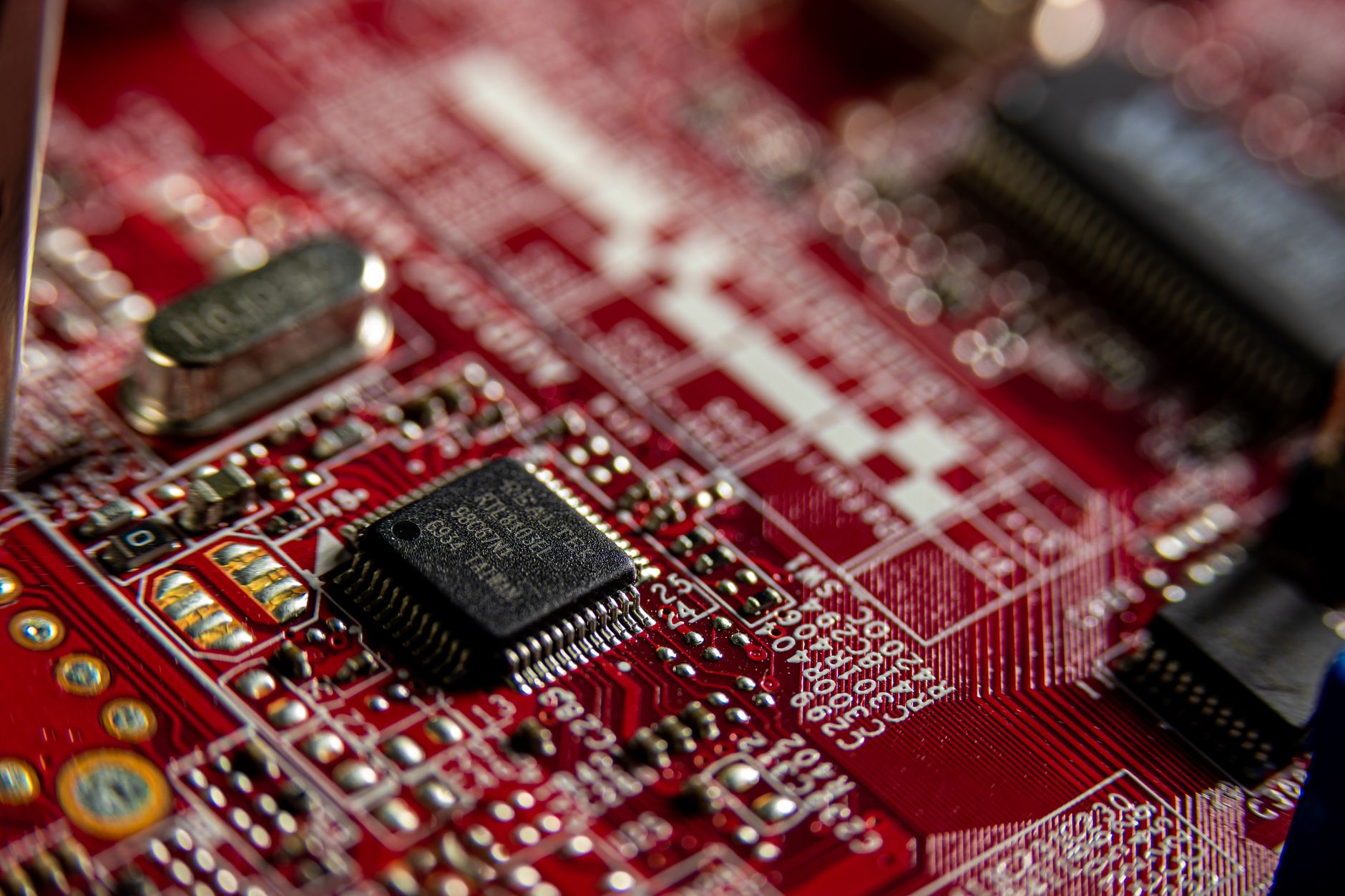
Battery Management Systems: The Engineering Layer Behind Lithium Battery Safety at Sea
What a BMS is, whether it’s mandatory, how it protects against thermal runaway, and how UN 38.3 and the IMDG Code actually require it — in practice, if not always by name.
Every consignment of lithium batteries that clears an IMDG Code shipment desk carries a UN 38.3 test summary, a set of watt-hour and lithium-content limits, and a stack of packaging and marking requirements. What rarely gets discussed openly — even though it sits behind almost every one of those requirements — is the small circuit board doing the actual work of keeping the battery from destroying itself. That board is the battery management system, or BMS.
What is a Battery Management System?
A battery management system is the electronic control layer built into, or fitted onto, a rechargeable battery pack. It sits between the individual cells and the outside world, continuously watching voltage, current and temperature, and stepping in the moment any of those values drifts outside a safe window.

At the simplest end of the scale, a single-cell battery (a coin cell in a wristwatch, say) might need nothing more than a fuse or a PTC device to stay safe. The moment cells are connected in series or parallel to build useful voltage and capacity — which is every e-bike, e-scooter, laptop, power tool, or battery-powered vehicle battery in commercial use — a fuse alone can no longer do the job. No two cells in a pack age, charge or discharge identically. A BMS exists to manage that inequality.
What exactly is a PTC device?
A PTC device (Positive Temperature Coefficient device, sometimes called a PTC thermistor or a polymeric PTC resettable fuse) is a small passive component, usually wired in series with the cell’s positive terminal. Under normal conditions it has very low resistance and barely affects performance. If the current through it rises abnormally — from an internal fault, an external short circuit, or overheating — the device itself heats up, and its resistance climbs sharply. That rise in resistance chokes off the current, before the cell reaches a dangerous temperature.
Two features make the PTC useful in lithium cells specifically:
- It is self-resetting. Unlike a one-time fuse, a PTC device cools down and returns to low resistance once the fault clears, letting the cell resume normal operation without being permanently disabled.
- It is passive and built into the cell. Most cylindrical lithium-ion cells (an 18650 cell, for example) have a PTC disc built directly into the cell can itself, ahead of any external circuitry — it protects the cell even before a BMS or PCM comes into play.
A PTC device on its own only addresses over-current and over-temperature. It does nothing for overcharge, over-discharge, or cell balancing across a multi-cell pack — which is exactly why a single PTC-protected cell can satisfy IMDG’s short-circuit protection requirement, while a multi-cell rechargeable battery needs the fuller function set of a BMS or PCM on top of it.
Its core functions are:
- Voltage monitoring — tracking each cell (or group of cells) individually, not just the pack as a whole
- Current monitoring — watching for charge and discharge currents that exceed the cell’s rated limits
- Temperature sensing — using thermistors placed at the cells or busbars to detect abnormal heating
- Cell balancing — bleeding or redirecting charge so that no single cell in a series string is pushed harder than the rest
- State of charge / state of health estimation — and, on more advanced systems, reporting that data out over a communication bus
A simpler cousin of the BMS, often called a protection circuit module (PCM) or protection circuit board (PCB), handles only the cut-off functions — overcharge, over-discharge, over-current and short circuit — without balancing or reporting. In small consumer batteries the two terms get used loosely, but the distinction matters when you are assessing what a given battery is actually capable of protecting itself against.

Is a BMS mandatory for lithium batteries?
Here the honest answer is: not by that name, but functionally, yes, for any multi-cell rechargeable battery — and that holds across all three chemistries the IMDG Code now regulates under this framework: lithium metal, lithium-ion, and, since Amendment 42-24, sodium-ion.
Neither the UN Model Regulations nor the IMDG Code contain a clause that reads “batteries shall be fitted with a battery management system.” What they do mandate is that every cell and battery offered for transport:
- must be of a design type that has passed the eight tests of the UN Manual of Tests and Criteria, Sub-section 38.3;
- must include a safety venting device, or be designed to prevent violent rupture under normal conditions of transport; and
- must be equipped with an effective means of preventing external short circuits.
For lithium metal (UN 3090/3091) and lithium-ion (UN 3480/3481) batteries, these three requirements sit at 2.9.4.1, 2.9.4.2 and 2.9.4.3 of the Code. Amendment 42-24 carried the identical structure over to sodium-ion batteries (UN 3551/3552), which now have their own dedicated section 2.9.5 — 2.9.5.1 (testing), 2.9.5.2 (safety venting/design) and 2.9.5.3 (short-circuit prevention) — worded almost clause-for-clause the same as the lithium provisions. Special Provision 230, the general provision attached to these fully-regulated entries, and Special Provision 188, the separate conditional exemption for small cells and batteries, were both extended by Amendment 42-24 to cover sodium-ion alongside the two lithium chemistries — though the two provisions still do different jobs: SP 230 underpins the fully-regulated shipment, while SP 188 is what gives a small battery relief from most of the rest of the Code. So the “functional BMS mandate” isn’t a lithium-ion peculiarity: it applies equally to a multi-cell lithium metal battery pack and to a multi-cell sodium-ion pack, because the underlying short-circuit and venting requirements they must satisfy are the same.
A clarification on button cells
Button cells (and the slightly larger coin cells) — the type used in watches, calculators, key fobs, and small medical devices — are a genuine exception to most of the above, and worth separating out clearly. Most button cells are single-cell, non-rechargeable primary cells; a smaller number are rechargeable secondary cells. Because a button cell is a single cell rather than a multi-cell assembly, there is no series string to balance and, for primary cells, no overcharge scenario to guard against in the first place — so the short-circuit protection requirement is routinely met with a simple internal protection device (a PTC, or the cell’s own internal current-interrupt design) rather than a full BMS.
Where button cells do intersect with the Code is on marking, not on the design mandate. SP 188 and the parallel IATA provisions exempt packages containing only button cells installed in equipment — and packages of no more than four cells or two batteries installed in equipment, up to two packages per consignment — from the lithium battery mark. This is a documentation and labelling relief, not a relief from 2.9.4.1–2.9.4.3 (or 2.9.5.1–2.9.5.3 for sodium-ion): the cell or battery still has to be a UN 38.3-tested type with effective short-circuit protection and safe venting. Rechargeable button cells still go through Test T.7 like any other rechargeable cell; they simply don’t need the balancing and multi-cell monitoring functions that make a full BMS necessary in a larger pack.
How the BMS contributes to safety
Thermal runaway — the self-sustaining, cell-to-cell heat and gas release that turns a battery fault into a fire — is the hazard every downstream IMDG Code provision on lithium batteries (stowage, packaging, fire-fighting appliances) is ultimately built around. The BMS is the layer that is meant to stop that sequence before it starts, well before packaging or stowage ever comes into play.

| BMS function | Failure it prevents |
|---|---|
| Overcharge cut-off | Lithium plating, gas build-up, and venting or fire from charging past the cell’s maximum voltage |
| Over-discharge cut-off | Copper dissolution inside the cell, which can cause an internal short on the next charge cycle |
| Over-current / short-circuit isolation | Rapid heating from excessive current draw or an external short across the terminals |
| Thermal monitoring | Undetected heat build-up progressing into self-sustaining thermal runaway |
| Cell balancing | One weak cell in a series string being driven outside its safe window while the rest of the pack looks normal |
| State of health reporting | A degraded or damaged battery being accepted for carriage without the operator knowing its true condition |
That last row has a direct regulatory echo. IMDG’s damaged and defective battery provisions (Special Provision 376) exist precisely because a battery that looks intact from the outside can be internally compromised. A BMS with proper diagnostic reporting is one of the few tools that can flag that condition before the battery is packed for shipment.
How UN 38.3 mandates a BMS — and how it doesn’t
UN 38.3 is a design type-qualification test regime, not a design standard. It doesn’t instruct a manufacturer to fit a BMS. What it does is test whatever protection the battery already has — and that’s where the mandate becomes practical rather than literal.
Of the eight tests in the series (T.1 to T.8), Test T.7 — Overcharge — applies specifically to rechargeable batteries. The battery is charged at up to twice its rated current for 24 hours, then observed for seven days, using whatever overcharge protection is fitted. To pass, there must be no fire, no explosion and no disassembly.
Read together, 2.9.4.1 (mandatory type testing), 2.9.4.2 (safety venting or rupture-resistant design) and 2.9.4.3 (short-circuit protection) form a closed loop: no battery type reaches a valid test summary without surviving T.7, and no multi-cell rechargeable battery survives T.7 without a BMS doing the work. That is the real mechanism behind the phrase “UN 38.3 mandates a BMS” — accurate in effect, but worth stating precisely rather than as regulatory shorthand.
Test-by-test applicability across the three chemistries
The eight tests don’t apply uniformly to every cell and battery. The applicability rule is actually the same across lithium metal, lithium-ion and sodium-ion — it depends on whether you’re looking at a bare cell or an assembled battery, and whether the item is rechargeable — not on the chemistry itself. The table below sets that out, and marks the two tests where the BMS or protection circuit is what’s actually being put on trial.
| Test | What it simulates | Li-Metal Cell | Li-Metal Battery | Li-Ion Cell | Li-Ion Battery | Na-Ion Cell | Na-Ion Battery | BMS / protection circuit relevant? |
|---|---|---|---|---|---|---|---|---|
| T.1 Altitude Simulation | Low pressure at high altitude | Yes | Yes | Yes | Yes | Yes | Yes | No |
| T.2 Thermal Test | Rapid cycling between temperature extremes | Yes | Yes | Yes | Yes | Yes | Yes | No |
| T.3 Vibration | Vibration experienced during transport | Yes | Yes | Yes | Yes | Yes | Yes | No |
| T.4 Shock | Mechanical shock / sudden impact forces | Yes | Yes | Yes | Yes | Yes | Yes | No |
| T.5 External Short Circuit | Short across the terminals at elevated temperature | Yes | Yes | Yes | Yes | Yes | Yes | Yes — evaluates whether the protection circuit (PTC, fuse, or BMS current cut-off) actually interrupts or limits the current |
| T.6 Impact / Crush | Mechanical deformation of the cell case | Yes | No | Yes | No | Yes | No | No — cell-level only; any protection here is an in-cell PTC, not the pack-level BMS |
| T.7 Overcharge | Forced charge at up to 2× rated current for 24 hours | No | No* | No | Yes | No | Yes | Yes — this is the test that directly puts the BMS’s overcharge cut-off to work |
| T.8 Forced Discharge | Forced reverse-current discharge past zero volts | Yes | No | Yes | No | Yes | No | No — cell-level only |
* Lithium metal batteries are almost always primary (non-rechargeable), so T.7 doesn’t apply to them in ordinary commercial practice. UN 3090/3091 does not prohibit a rechargeable lithium metal battery; if one exists, T.7 applies to it exactly as it would to any other rechargeable battery. Lithium-ion and sodium-ion batteries, by definition, are always rechargeable, so T.7 always applies to them. Note also that a single cell packaged and marketed as a “battery” with its own protection circuit is tested as a battery for T.7 purposes, not as a bare cell.
Two things stand out from that table. First, T.5 and T.7 are the only tests where the protection circuitry itself is on trial — every other test is evaluating the cell’s mechanical and thermal construction, independent of whatever electronics sit outside it. Second, T.6 and T.8 are cell-level tests that a finished, BMS-equipped battery never has to face directly — which is worth knowing if you’re ever comparing a cell manufacturer’s test summary against a battery assembler’s, since the two won’t list the same set of passed tests.
One further refinement, for completeness, and it actually strengthens the point this article is making. Where a large battery is assembled from smaller batteries that have already individually passed the full T.1–T.8 series, the Manual applies one of two rules depending on size. Under Sub-section 38.3.3.1(f), an assembly at or below 500 g lithium content (lithium metal) or 6,200 Wh (lithium-ion) must still be tested at the assembly level — T.3, T.4, T.5, and T.7 if rechargeable — even though T.1 and T.2 aren’t repeated. Under Sub-section 38.3.3(g), an assembly above that threshold does not need to be tested at the assembly level at all — but only if it is equipped with a system capable of monitoring the assembly and preventing short circuits, over-discharge, overheating and overcharge across it. That’s a battery management system in every sense but name, and for the largest lithium and sodium-ion assemblies — containerised energy storage systems, vehicle-scale packs — its presence is literally what the Code accepts in place of re-testing the whole assembly.
Connecting it to IMDG Code transport safety
Once a container is loaded aboard a vessel and the ship is at sea, the options for fighting a deep-seated lithium battery fire inside a stack of containers are limited compared with a shore-based response. That single operational reality is why the entire regulatory chain — UN 38.3 type testing, the IMDG 2.9.4 design provisions, packing instructions and stowage requirements — is weighted so heavily toward preventing ignition rather than managing it after the fact.

The BMS is the first and, arguably, the most important layer in that chain. Packaging and stowage are there to contain a failure that has already started, or to buy time for it to be detected. The BMS is designed to stop the failure from starting at all. For anyone reviewing a lithium battery shipment — a DG officer, a freight forwarder, a surveyor — the UN 38.3 test summary is, in effect, the paper trail confirming that this first layer of defence was in place and functioning when the battery type was certified.
Understanding that chain — BMS, to UN 38.3 T.7, to the IMDG 2.9.4 design provisions, to packing and stowage — is what separates a shipment that merely has the right paperwork from one where the paperwork actually reflects a battery built to survive the voyage.
Discover more from IMDG Code Compliance Centre
Subscribe to get the latest posts sent to your email.